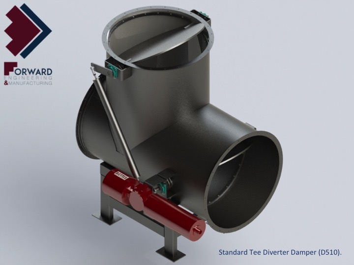
Standard Tee Diverter Damper – D510
Forward Engineering & Manufacturing LLC diverter dampers are engineered with state of the art design features to all applicable codes and standards including ASME Boiler and Pressure Vessel Code, ASTM and AISI.
FE&M offers four types of diverter dampers for virtually all gas turbine combined cycle application:
- Standard Tee Diverter
- Standard Multi-Blade Louver Diverter
- Single Flap Diverter with Direct Drive
- Single Flap Diverter with Link Drive.
- Engineering Experience – With over 40 years engineering experience, FE&M has a deep understanding of gas turbine simple cycle and combined cycle applications of all types of diverter dampers, WHRU stack dampers, expansion joints, and Selective Catalytic Reduction (SCR) equipment. Customers can be assured of FE&M using all its experience in providing you with only the best in damper design for your specific gas turbine application. Engineers use design simulation (FEA), SolidWorks and AutoCAD to ensure reliable component design and accurate ‘fit up’ during product manufacture.
- Engineered for Service Longevity – All FE&M diverter dampers are carefully engineered and manufactured to highest quality standards to assure installed performance and longevity. High-temperature transients and turbulent gas flow during startup demands attention to every detail. Blade/Flap assembly, shafts, links, bearings, seals, packing glands, internal liner system and frame design is critical to assembly performance and longevity.
- Blade/Flap Assembly –
- Standard Tee Diverter blades are engineered for high transient temperatures utilizing flat mill plate with or without stiffener. Stiffener designs reduce thermal gradients and thermal stresses.
- Multi-Blade Diverter blades is a welded semi-monocoque structure designed to reduce thermal gradients and stresses.
- Single Flap Diverter utilizes a hinged flap designed to isolate either diverter outlet. The flap is engineered with a rigid sub-structure and two insulated face panels. The sub-structure is exposed to gas reducing thermal gradients and stresses. Each face panel is allowed to expand and contract in response to transient temperatures eliminating thermal stress and distortion.
- Shafts – Shafts are designed to transmit maximum torque and support all live and dead loads with appropriate safety factors per ASME. Thermal transients on startup require shafts and shaft connections be designed such that transient thermal stresses are reduced.
- Connecting Links – Single Flap Diverters with link Drive require use of connecting links with custom spherical pivot bearings to allow for transient thermal growth of flap, links and shaft during startup. Bearings are metal alloy sleeve bearings with plugged graphite. Tee Diverter and Multi-Blade Diverter dampers use external connecting links between dampers with spherical rod ends at each end to allow for misalignments.
- Seals –
- Standard Tee Diverter Seats – Bulb and metal seats are all designed for maximum longevity in gas turbine service. Seats are easily replaceable from the interior of the damper. Bulb seats are designed to withstand 2,300 degrees F and static pressures exceeding 5 psi. Bulb seats feature Inco 600 cores and woven ceramic fiber jackets with type 316 stainless steel knitted wire outer wrap.
- Flap Diverter Seals – Flap diverter seals are fabricated from nickel alloys known for high strength and fatigue resistance at elevated temperatures. Seals are engineered for thermal transients and long term exposure to turbulent high-temperature gas. present in harsh gas turbine exhaust environment.
- Bearings – Self-lubricating sleeve bearings positioned at least 6” from frame exterior outboard of packing glands are standard on small diverter dampers. Medium to large diverter dampers will require metal alloy sleeve bearings with plugged graphite for all high temperature gas turbine applications.
- Packing Gland – The standard packing gland for small diverters is a 2-bolt design having formed packing rings, the number of which depends on the maximum design pressure. Leakage through the packing gland is zero (0) at any blade position at maximum design pressure. Medium to large diverters require use of a larger gland design also packed with high-temperature graphite packing.
- Internal Liner System – Internal lining system is composed of layers of 8 pound per cubic foot ceramic fiber insulation retained by 0.125” thick 409 stainless steel liner panels. Liner panels are held in place but allowed to freely expand and contract using ½” diameter threaded studs, hold down washers and seam channels. Panels are ‘ship-lapped’ in the direction of flow and seams are covered with seam channels to ensure a tight, vibration-free liner.
Diverter frames are carefully engineered and fabricated to ensure precise dimensional tolerances are maintained for each application. Damper bodies are designed to provide rigid platforms on which the damper reliably isolates and diverts flow. Flap Diverter bodies are internally lined to reduce heat loss while providing the least possible static pressure loss. Frames are engineered considering flange loads, dead loads and all live loads with blades/flap in any position between isolating waste heat recovery equipment and bypass stack. Combined bending, shear and thermal stresses are within ASME allowable stress values.
Leave a Reply
Want to join the discussion?Feel free to contribute!